How to Install a Machine on Anti-Vibration Mounts Without a Foundation
To install a machine on anti-vibration mounts, confirm that its manual allows installation without a foundation and that the floor is solid, intact concrete, put one mount under each support point of the bed (the foundation bolt holes), lower the machine evenly and level it with the mount's stud and nut. Then tighten the lock nuts, add fixators against shifting if needed and re-check the level after the first days of operation.
When a machine can stand on mounts without a foundation
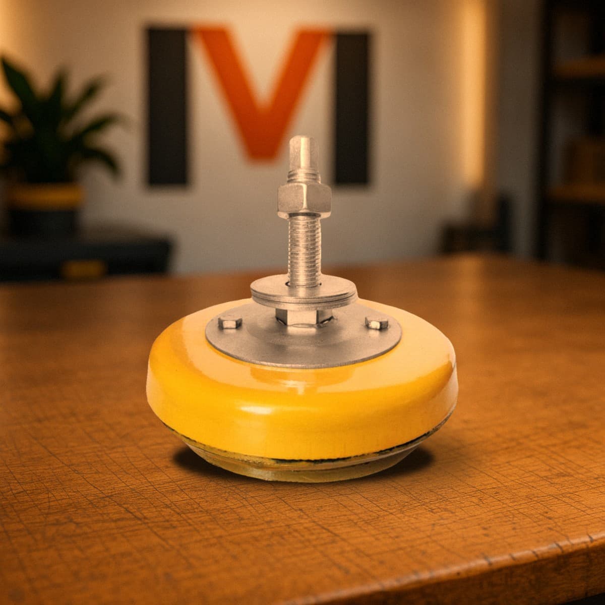
An anti-vibration mount is a rubber-metal pad with a threaded stud that the bed rests on instead of foundation bolts. The rubber damps vibration between the machine and the floor, and the stud lets you level the machine. Most medium-size lathes, milling, drilling and grinding machines with a rigid bed are installed this way - with no separate foundation, directly on the concrete shop floor.
First, open the machine's passport or operating manual and find the installation section. It states whether the manufacturer allows mounts, how many support points the bed has and how to level the machine. If the manufacturer requires a foundation or anchor bolts, mounts do not replace them. More on that choice in mounts or a foundation.
Second, mass. Each mount has a working load range, and the load on it must be no less than the minimum and no more than the maximum. How to choose the mount type is covered in the guide to choosing anti-vibration mounts for machines; this article is about the installation itself.
- The machine manual allows installation on mounts (or does not require a foundation).
- You know the machine mass with tooling and the number of bed support points.
- The floor is solid concrete with no voids or cracks at the mount locations.
- You have lifting means: a crane, hoist or jacks, and slings with the manual's slinging diagram.
Step 1. Check the floor under the mounts
A mount transfers the whole weight of the machine onto a small area. The OV-31M pad is 140 mm in diameter, about 154 cm². If a mount carries 2000 kg, the floor pressure is roughly 13 kgf/cm² (about 1.3 MPa). For a solid concrete shop floor this is a moderate load, but tiles on a thin screed, old asphalt or a wooden floor can crack or sink, and the machine will lose its level over time.
Inspect the mount locations. Tap the floor: a hollow sound under tiles or screed means a void. A crack under a mount means future settling. If the shop floor has a step or slope, measure it in advance: the OV-31M height adjustment is 12 mm, and a larger difference cannot be taken up by the mount.
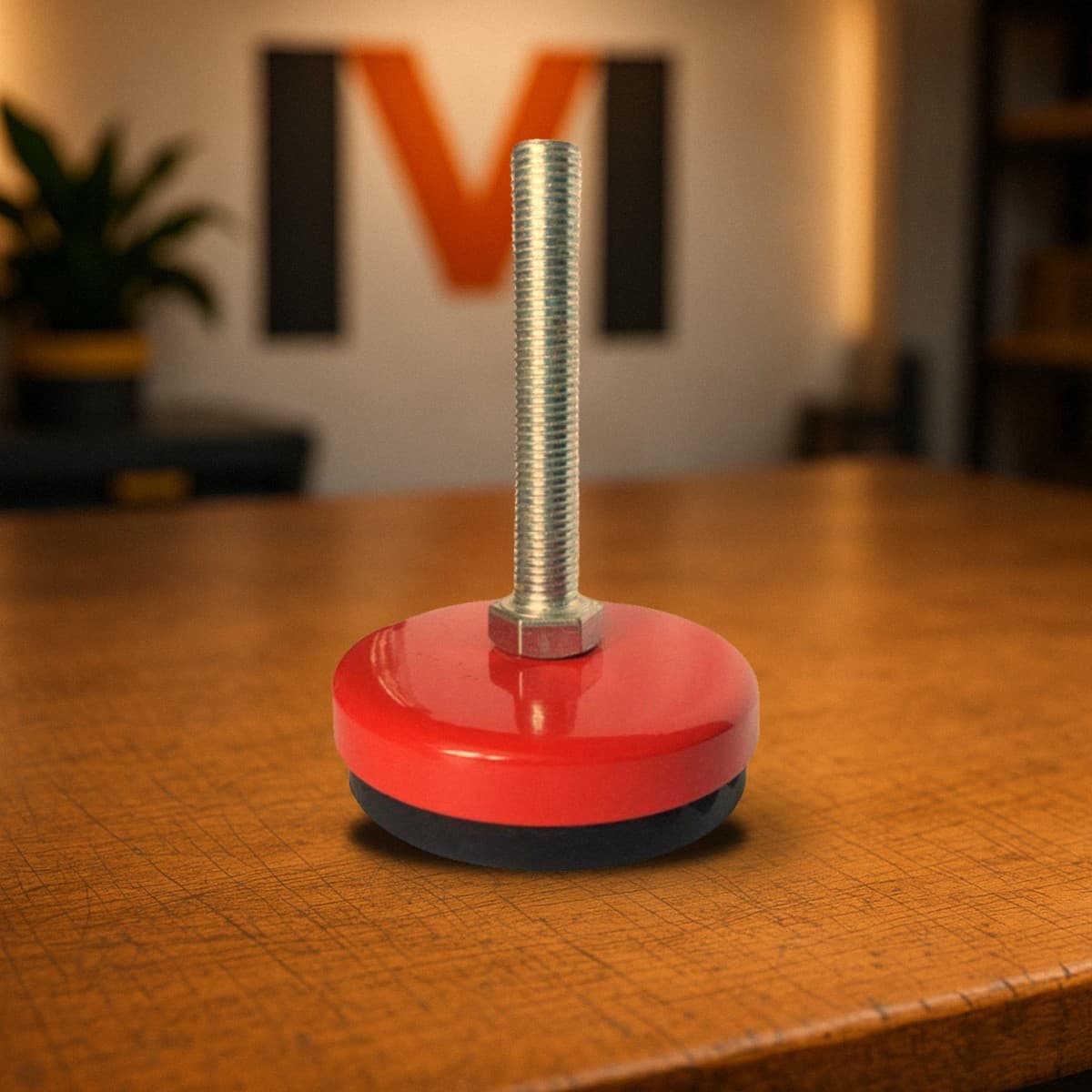
On a noticeably uneven or inclined base where a standard mount does not sit on its full pad, consider hinged anti-vibration mounts such as the IV M12 - their stud is hinged to the body, so the pad stays flat on the floor even when misaligned.
- Concrete without voids or cracks under each mount.
- No tiles on thin screed, asphalt or wooden decking under the mounts.
- Height difference between support points within the mount's adjustment range.
- No hatches, trenches or pipes in the floor under the mounts.
Step 2. How many mounts and where to put them
Mounts go under the bed's support points - usually the foundation bolt holes in the machine's feet or base. As many holes, as many mounts: the stud passes through the hole and the foot rests on the mount. The support point layout is on the installation drawing in the manual. Do not place mounts wherever is convenient - the bed is designed to be supported at those points.
Next, check the load on each mount. Divide the machine mass with tooling by the number of mounts - that is the average. But the mass is not even: a lathe's headstock is heavier, a milling machine's knee and table are heavier. So mounts under the heavier end carry more. How to calculate this, with examples, is in how many anti-vibration mounts a machine needs.
Each mount must work inside its range. Below the minimum it is too stiff for that mass and does not work as designed; above the maximum it is overloaded. For the models in our machine components section the ranges are:
| Model | Load per mount | Stud | Pad | Height adjustment | Price |
|---|---|---|---|---|---|
| OV M12 | 40-250 kg | M12 | 80 mm | not provided | from ~684 UAH excl. VAT |
| IV M12 (hinged) | 40-250 kg | M12 | 55 mm | see product page | from ~620 UAH excl. VAT |
| OV-31M | 250-4500 kg | M16 | 140 mm | 12 mm | from ~1,085 UAH excl. VAT |
Step 3. Lifting the machine safely onto the mounts
Lift the machine as the manual says: with a crane or hoist following the slinging diagram, or with jacks at the points intended for it. Take the mass from the manual and check sling capacity and angle with the sling load calculator. If the machine was bought second-hand without a manual, see what to check in used or new machine.
Before lowering the machine, set all mounts to the middle of their adjustment so there is travel both up and down. Engage the studs in the foot holes and lower the machine slowly and evenly so it sits on all mounts at once instead of dropping onto one.
- Never sling by the spindle, chuck, lead screw, shafts, handles or ways.
- Never work under a suspended machine; use solid stands if you must work underneath.
- Place mounts before lowering, do not knock them under a machine already down.
- Lower without jerks: an impact on the rubber pad can damage it.
- Check that every pad sits on the floor with its full area.
Step 4. Levelling the machine with the stud and nut
Levelling needs a machinist's level (bar or frame type) with the scale division required by the machine manual. A builder's level is not suitable. Where to place the level is also in the manual: on a lathe usually the bed ways, lengthwise and crosswise; on a milling machine, the table.
Height is changed with the mount's adjusting unit - the stud and nut (12 mm range on the OV-31M mount). First roughly level crosswise, then lengthwise. Adjust a little at a time, mount by mount, and re-place the level after each step. For the adjusting unit design and OV-31M dimensions, see OV-31M mount specifications.
The main trap with long beds is twist. With six or eight support points you can get the ends level while a middle mount is under- or overloaded, and the bed twists. So check the level at several positions along the bed (on a lathe, by moving the carriage), not only at the ends. Tolerances come only from the machine manual; for precision machines such as the 16K20 lathe they are given in the installation section.
When the level is within limits, tighten the lock nuts without disturbing the adjustment and check the level once more after tightening.
- Start with all mounts at mid-adjustment.
- Crosswise level first, then lengthwise, then check along the whole bed.
- No mount may hang free: make sure each one carries load.
- Re-measure after tightening the lock nuts.
Step 5. Fixator against shifting and a re-check after run-in
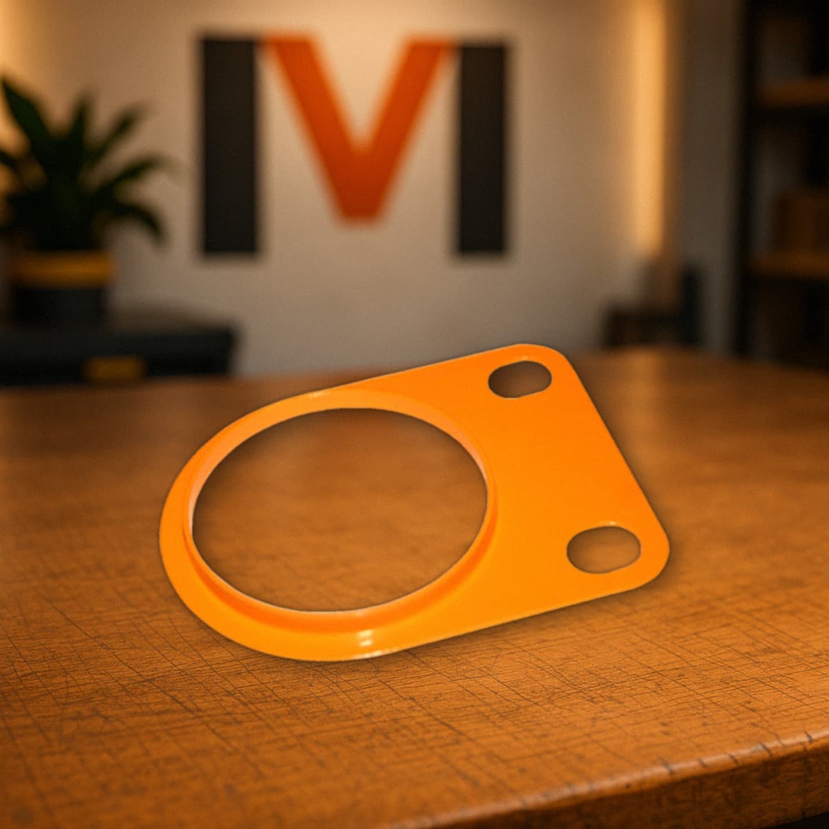
In operation a machine on rubber can slowly creep across the floor, especially under impact or alternating loads, as with presses. The OV-31M mount fixator secures installed equipment against shifting. Its dimensions A 180, B 140, C 119, D 18 mm suit a mount with a 140 mm pad; price from ~345 UAH excl. VAT each. Ask us how to fix it to your floor when ordering.
Rubber under load settles slightly over time, so the level after the first installation is not final. Check it after the first days of operation and readjust, then periodically or whenever machining accuracy changes. If the machine manual sets a re-levelling procedure, follow it.
Also check what you installed the mounts for: whether vibration on neighbouring equipment and on the part went down. More in the article on equipment vibration isolation.
Typical mistakes when installing a machine on mounts
These mistakes most often cancel the benefit of mounts or spoil machine geometry:
- Mount not chosen by load: a light OV M12 under a heavy headstock, or a heavy OV-31M under a machine putting less than 250 kg on each mount.
- Mounts placed not under the bed's support points but wherever they ended up.
- A long bed levelled only at the ends, and it twisted.
- One mount carries no load - the machine stands on three of four mounts.
- Mounts on tiles, on screed with voids or at the edge of a trench.
- Level not re-checked after the rubber settled, and the cause of tapered parts was then searched for in the machine.
Checklist: installing a machine on anti-vibration mounts
Print the table and go through it in order. To select mounts for a specific machine, send the model and mass via the quote request.
| Step | What to do | How to check |
|---|---|---|
| 1 | Find the installation section in the manual | Mounts allowed, number of support points known |
| 2 | Calculate the load on each mount | Each mount within its range, heavier end included |
| 3 | Inspect the floor at mount locations | Concrete without voids or cracks, height difference within adjustment |
| 4 | Set mounts to mid-adjustment | Travel available up and down |
| 5 | Lift and lower the machine evenly | Slinging per manual, all pads fully seated |
| 6 | Level the machine | Crosswise, lengthwise and at several bed points - within manual limits |
| 7 | Tighten lock nuts, fit fixators | Level unchanged after tightening |
| 8 | Re-check after run-in | Level and machining accuracy within manual limits |
FAQ
Can a lathe be installed on anti-vibration mounts without a foundation?
Yes, most medium-size lathes with a rigid bed are installed on mounts directly on a concrete floor. Check that the manual does not require a foundation and that the load on each mount is within its working range.
What do I level a machine on mounts with?
A machinist's bar or frame level with the scale division specified in the machine manual. Height is adjusted with the mount's stud and nut, within 12 mm on the OV-31M.
What is an anti-vibration mount fixator for?
It secures installed equipment against shifting across the floor in operation. For the OV-31M its dimensions are A 180, B 140, C 119, D 18 mm.
How many mounts go under a machine?
As many as the bed has support points on the installation drawing - usually one per foundation bolt hole. Then check that the load on each mount is between its minimum and maximum.
When should the level be re-checked?
After the first days of operation, when the rubber has settled under load, then periodically or when accuracy drops. If the machine manual sets a different procedure, follow it.