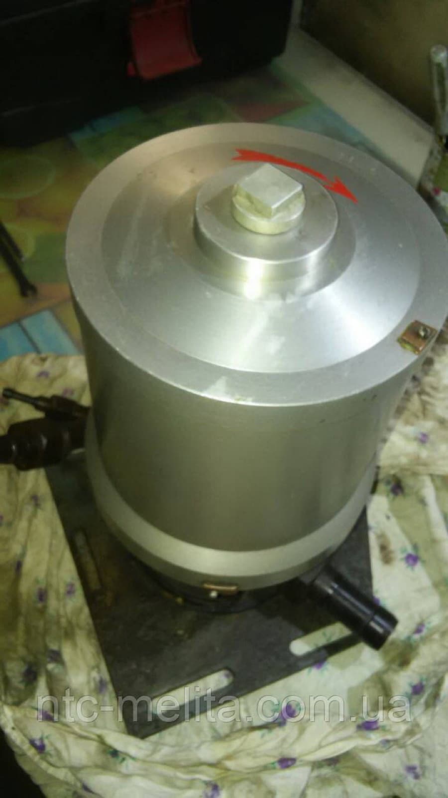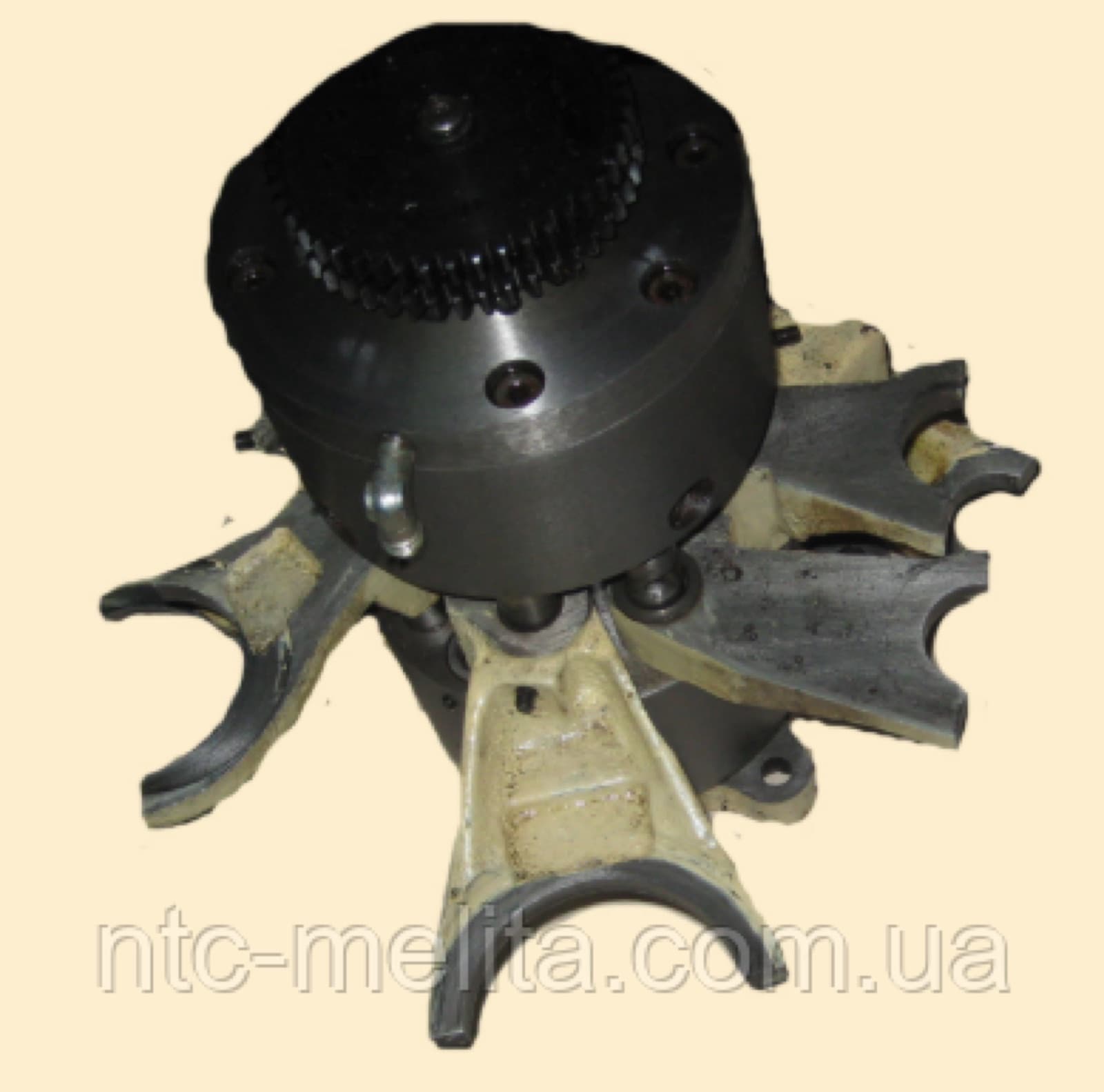
Hydraulic preselector 2A554
65 836,80 ₴incl. VAT
54 864 ₴ excl. VAT · invoice for companies and sole proprietorsGet an invoice or a quote
Nova Poshta, Meestat the carrier's rate
Freight carrierat the carrier's rate
Pickup, Dniprofree
Specifications
| Main | |
|---|---|
| Manufacturer | Odesa Radial Drilling Machine Plant |
| Country of origin | Ukraine |
| Component type | Gearbox |
Description
The hydraulic preselector is a unit in the upper housing of the drilling head that shifts the gears of the speed and feed gearbox. It provides preselective control: the operator sets the next machining mode on the handles in advance while the machine runs in the current one, and pistons with shift forks move the gears under oil pressure. This cuts auxiliary time spent on machine control.
This preselector assembly is intended for the 2A554 radial drilling machine, designation 2A554.50.45.000. Manufacturer: Odesa radial drilling machine plant, Ukraine. Suited to maintenance teams and workshops that need to restore speed shifting on this model.
Hydraulic preselector for radial drill 2 A554 2A554.50.45.000
The operating principle of the hydraulic preselector and its drive is described below.
The drilling head is equipped with an electro-hydraulic mechanism for preselective control of the speed and feed gearbox. Preselective control means that the required machining mode is set on the control handles in advance, while the machine is operating in another mode. Such control reduces the auxiliary time associated with operating the machine.
Fig. 47 shows the design of the hydraulic preselector, and Fig. 48 shows the design of its drive.
The gears are shifted by the actuator - the hydraulic preselector, located in the upper housing of the drilling head and forming (Fig. 47) a self-contained unit. Housing 1 of the hydraulic preselector is an iron casting with sleeve 2 pressed into its central bore. Channels are milled and holes are made on the surface of this sleeve to pass oil in the required direction. These channels match the corresponding millings of top cover 3 and base 4, which are attached to housing 1 with screws.
Around the central bore of housing 1 there are holes that act as hydraulic cylinders. Cast iron shift forks 6 are fitted and pinned on pistons 5; their cheeks engage the grooves of the corresponding gears of the speed and feed gearbox. Depending on the direction of oil flow, pistons 5 take the upper or lower position. The machine's two triple gear blocks must have a fixed middle position in addition to the end positions. Additional pistons 7, with a diameter larger than pistons 5, provide the middle position. As a result, when pressure is applied simultaneously to the cavity of piston 7 and the opposite cavity of piston 5, the block travel is determined by the travel of piston 7, which equals half the travel of the triple gear block.
Pistons 8 are acted on by springs 9, which tend to press them against bushing 10. The rods of pistons 8 then move the fork of gears 30-30 mounted on the machine spindle, thus disconnecting the spindle from the gearbox; when there is oil pressure in the system, the oil enters the cylinders and, overcoming the resistance of springs 9, moves pistons 8 to their end positions. To allow preselection of speed and feed, there is no oil pressure in the hydraulic preselector while the machine is running; it is switched on only briefly to shift the gears. To hold the gear blocks in the selected position, pistons 5 have detent grooves into which balls 11 of detent 12, backed by springs 13, engage. These springs are designed for small forces so as not to hinder the movement of the pistons when the gear blocks shift. During machine operation, in addition to the mass of the gear blocks, pistons 5 and forks, the detents are subject to dynamic loads caused by vibration and other factors, and the force of spring 3 may be insufficient to hold the gear blocks in the selected position. Therefore, pressurized oil is supplied under detents 12 through special holes and is released only while speeds are being shifted.
The central bore of the hydraulic preselector houses two rotary valves - spindle speed selector 14 and feed rate selector 15. Their shape directs oil through the holes and channels of sleeve 2, cover 3 and base 4 into the shift cylinders.
To set the required spindle speed and feed rate, selectors 14 and 15 must be turned to the required position. This is done by motors 1 (Fig. 48) with built-in gear reducers, via couplings 2 mounted on the reducer output shafts, shafts 3 and gears 4-7, each with 46 teeth. The spindle speed is selected with handwheels, each of which has fixed positions corresponding to the number of spindle speed and feed steps.
Product reviews
All MELITA reviews →No reviews of this product yet. Bought it from us? Tell others how it works.
Similar items: Machine spare parts and components
Entire category →